Space and Time
Large parts of our software deal with spatial data and time measurements. This page gives an overview of the coordinate systems in use and the transformations of points/poses between them, as well as some hints regarding their usage. In addition, functions for measuring time are described.
Units for Space and Time
In general, distances are measured in millimeters in the B-Human system. Angles are measured in radians, but it is possible to specify them in degrees by adding the suffixes _deg (in C++ source files) or deg (in configuration files). Time is measured in milliseconds. Timestamps are measured relative to 100 seconds before the start of the B-Human software, i.e. time measurements start at 100 s (i.e. 100000 ms). This allows to distinguish them enough from timestamp 0, which is often used to indicate that no timestamp is available (yet) for a certain event.
Coordinate Systems
Field
The origin of the field coordinate system is the center of the center circle, which should coincide with the center dash. The x-axis points toward the center of the opponent's goal, the y-axis left along the halfway line (as viewed from the own goal), and the z-axis upward. In the figure below, the coordinate system applies to a team that plays on the goal outside the bottom left border of the image.
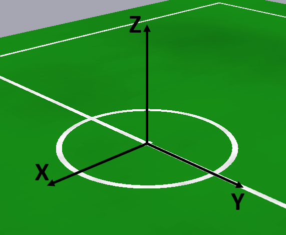
Variables that describe objects in this coordinate system often have the name suffix OnField, especially in the behavior. However, in other places (in particular in perception), OnField means something else (see below).
Note that the coordinate system depends on the goal on which the team is playing (e.g. it flips between the first and the second half with respect to the physical field). In particular in the simulator, in which two teams are playing, both teams have their own field coordinate system. The global simulator coordinate system (i.e. the one used in scene description files, the mvo command and some other places mostly in the SimulatedNao library) coincides with the field coordinate system of the second team.
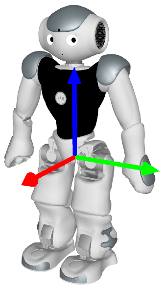
Robot
The robot coordinate system's origin is, roughly speaking, in the middle between the feet. More precisely, it is in the middle between the projections of the ankle joints on their respective foot soles. The z-coordinate of this coordinate system relative to the field coordinate system is defined as 0, which is only correct if at least one foot is aligned with the ground plane. The z-axis of this coordinate system is not tilted w.r.t. the field coordinate system (i.e. the x/y-plane of this coordinate system is the same as that of the field coordinate system – actually it is mostly used as 2D coordinate system in a top view). The coordinate system's rotation around the z-axis is aligned with the robot's upper body, i.e. the x-axis points forward from the robot's point of view.
In behavior code, variables containing objects in this coordinate system often have the suffix Relative. In perception, the suffix is often OnField.
Torso
The torso coordinate system's origin is in a fixed point relative to the robot, namely the center between the left and right hip joints. The x-axis points forward, the y-axis left (i.e. through the left hip joint), and the z-axis upward (i.e. through the neck joint).
In some parts of the code, especially motion/sensing, this coordinate system is also referred to as "robot coordinate system". It is important to note that this coordinate system does not coincide with Aldebaran's torso coordinate system (its origin is 85mm above ours).
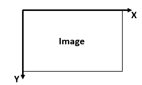
Image
The origin of the pixel coordinate system is in the upper left corner. The x-axis points to the right and the y-axis points down. It is important to note that due to the YUYV-format the width of the CameraImage is only half of CameraInfo::width. However, the methods get{Y,U,V,YUV} of the CameraImage still work with coordinates relative to the CameraInfo dimensions (i.e. each YUYV-pixel is counted as two pixels horizontally). The ECImage and other derived images also use the "full" horizontal resolution. In matrix/array-like image access, the y-coordinate is always the first index (due to the row-major storage order of the image).
There is also the corrected image coordinate system, which is not related via a Euclidean transformation with the pixel coordinate system. It compensates for the rolling shutter effect (i.e. each row is taken at a different point in time) and the fact that the joint angles / torso rotation used to calculate the camera pose are from yet another point in time.
Spatial Transformations
Given a point/pose in one coordinate system, one might want to get its coordinates in another system. Most transformations are represented via the relative pose of one system's origin in the other system's origin. They work both ways by using the .inverse() method. Only the transformations between camera coordinates and pixel coordinates are different. The following figure gives an overview:

The representations in the following table can be used like transformation matrices:
| Representation | is/contains |
|---|---|
RobotPose |
2D pose of the robot relative to the field |
TorsoMatrix |
3D pose of the torso relative to the robot (on the ground) |
RobotCameraMatrix |
3D pose of the camera relative to the torso |
CameraMatrix |
3D pose of the camera relative to the robot (on the ground) |
RobotModel |
3D poses/positions of limbs relative to the torso |
For example, to transform a point given in the robot ("relative") coordinate system into the field coordinate system:
pointOnField = theRobotPose * pointRelative
To transform a point from the field coordinate system into the robot coordinate system:
pointRelative = theRobotPose.inverse() * pointOnField
Of course these are only estimates, i.e. transforming a point between robot and field coordinates using the RobotPose depends on how accurately the robot currently knows its pose on the field.
The transformations between the corrected image coordinates and the pixel coordinates uses the methods fromCorrected and toCorrected of the representation ImageCoordinateSystem. To transform directly between robot coordinates and (corrected) image coordinates, there is the Transformation namespace (Tools/Math). The most important functions are imageToRobot and robotToImage. imageToRobot takes a point in (corrected) image coordinates and projects it into a 2D-point relative to the robot in the ground plane (if the point in the image is not on the ground imageToRobotHorizontalPlane can be used). robotToImage does the inverse, i.e. it takes a point in robot coordinates (either 2D in the ground plane or 3D with arbitrary height) and projects it to (corrected) image coordinates. The robotWithCameraRotation variants transform from/to a robot coordinate system that is rotated around the z-axis such that the x-axis points forward from the camera's point of view (instead of the torso's).
All objects that are stored in robot-relative coordinates (or represent robot poses) must be updated by odometry (i.e. the robot's estimate of its own motion). In the thread Cognition, there is the representation Odometer which provides the pose offset by which the robot coordinate system moved w.r.t. the field coordinate system within the last frame (as estimated by the motion controllers). Objects relative to the robot have to be multiplied by the inverse of this pose in order to stay at the same location on the field. Alternatively, the value of the representation OdometryData can be saved together with relative coordinates of an object, and when that object is later needed again, the pose difference of the current and saved OdometryData can be applied to get the object in current relative coordinates (currentRelativeCoordinates = theOdometryData.inverse() * oldOdometryData * oldRelativeCoordinates). This method should only be used if the Odometer cannot be used (e.g. if the code is not executed in every frame).
When transforming data between coordinate systems, velocities and covariance matrices should be considered as well. Since all objects (besides the ball) are modeled as being stationary, velocities only need to be rotated, e.g. using the rotate(d) method of Vector2f. Multiplying with the pose is wrong here because that would add the translation to the velocity. Covariance matrices need to be rotated as well, e.g. using Covariance::rotateCovarianceMatrix. Furthermore, the uncertainty of the reference pose (e.g. the pose of the robot) could be integrated (to account for the effect of the rotational uncertainty of the reference pose on the translational uncertainty of the target), e.g. by an Unscented Transform. However, this is not done anywhere in our code at the moment.
Measuring Time
Most parts of the code use the so-called frame time, i.e. the time when the data that is currently processed was read from the sensors (the camera image or the sensor data received from LoLA). FrameInfo is a representation available in all framework threads (as theFrameInfo). It has a field time that contains the timestamp in ms and a method getTimeSince that allows to determine the (signed) duration between another timestamp and this one.
There are two global functions that allow to measure time directly: Time::getCurrentSystemTime and Time::getRealSystemTime. On the robot, both do exactly the same, i.e. return the current time in ms. However, in the simulator, there is a mode in which time is only progressed with each simulation step. As a result, Time::getCurrentSystemTime returns a time that is proportional to the execution speed of the simulation. In contrast, Time::getRealSystemTime always measures the real time independent of the simulation speed. Analogous to the frame time, there also two functions Time::getTimeSince and getRealTimeSince.