Calibration
NAO
The B-Human software expects all parts of the NAO robot to be at specific positions, so it is very important that the robots are calibrated correctly. Uncalibrated robots will probably not be able to walk reliably and in a stable manner. Also, projections from image coordinates to world coordinates (and vice versa) will be wrong, resulting in a multitude of problems. Currently, three components of the robot, the IMU, the cameras, and an offset between the foot soles and the IMU, require calibration. We recommend checking the camera calibration from time to time, but especially all three calibrations after the robot was repaired. Even though we also provide a way to automatically calibrate the joints, we only perform such calibration if we assume the robot in question was calibrated incorrectly, e.g. after a repair. At the moment, none of our NAO\(^\mathsf6\) robots are in such a state, so we only calibrate the cameras and some sensors.
Autonomous Calibration
To perform the calibration, place the robot at the sideline of a soccer field, as if the robot would return from a penalty (in line with the penalty cross), facing the penalty cross.
Now you need to bring the robot into the calibration mode to start the autonomous calibration process. Press the robot's chest button once to bring the robot from the inactive state into the initial state (in which the robot stands upright). Press and hold the front head button and the chest button. After one second, the robot switches to the calibration mode, indicated by a blue-purple glowing chest button. Release both buttons.
Note
As long as the chest button shows no color, you can repeat the process. If the robot's chest button glows red (indicating the penalized state), you can press and hold all three head buttons for one second to bring it back into the inactive state. If the chest button glows green, press the button once to transition into the penalized state, from which you can then switch the robot back into the inactive state.
IMU
In general, the IMU is automatically calibrated whenever the robot is standing still on the ground during its normal operation. However, that calibration is only temporary. To force a calibration that is saved in a file during the automatic calibration process, the flag isCalibrated in the file imuCalibration.cfg must have been set to false, as it is in the default version of that file.
Camera Extrinsics
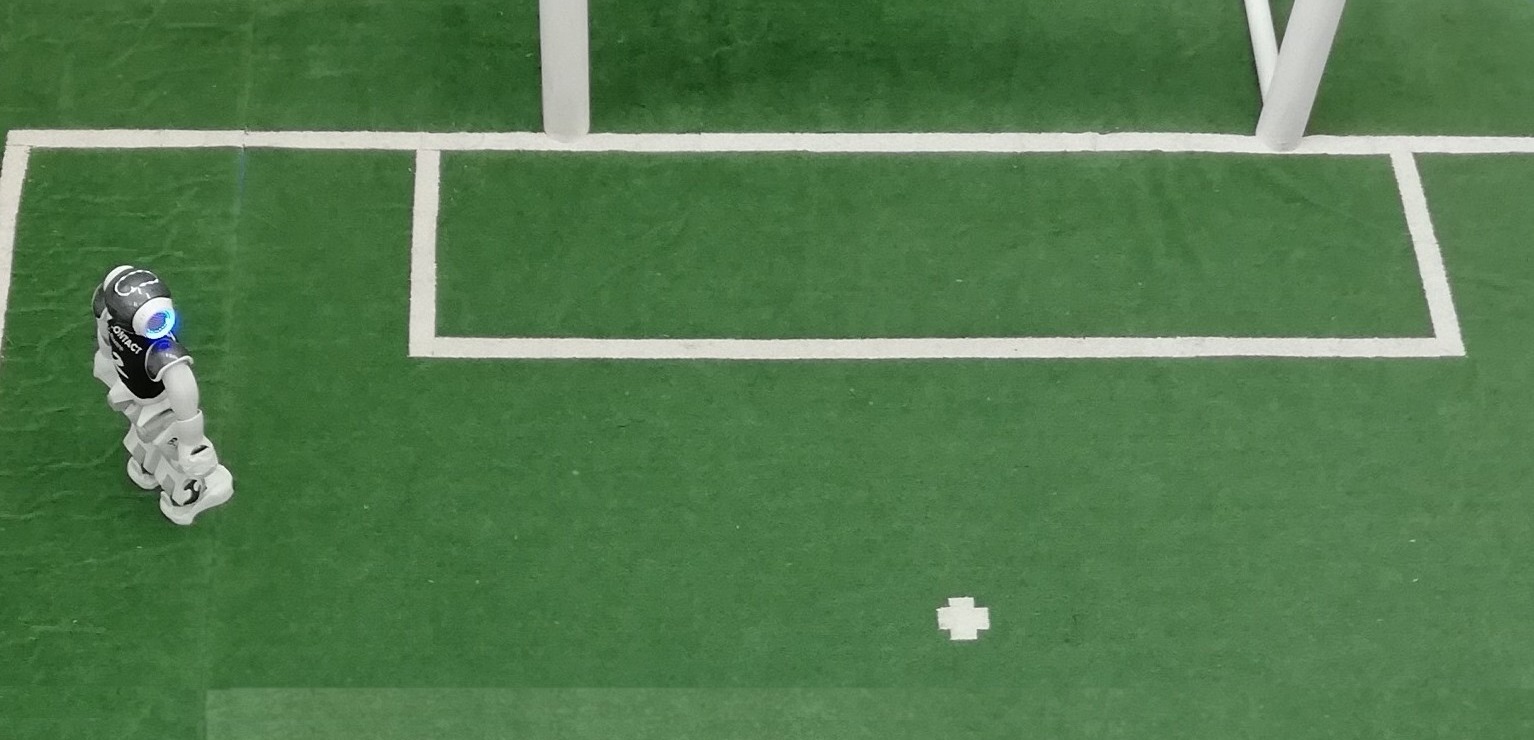
The robot will walk roughly to the position shown in the image.
The robot will attempt to detect some field lines of the goal area and turn twice. If the robot is unable to detect a field line, it will automatically move the head around or even reposition itself.
The robot will then stand still and optimize the calibration parameters. The resulting camera calibration will automatically be saved on the robot.
Note
If you stop the calibration process after some samples were already recorded, we recommend to restart the robot or deploy it again. The already sampled configurations are not deleted as long as the software is running.
Keeping the Calibrations
The results of the automatic calibrations are stored on the robot. To keep them permanently, they must be transferred to your computer, so that they will be used again when the software is deployed again to that robot. This can be achieved by either using the deploy dialog to connect to the robot and pressing the button download calibration or by running the underlying script directly:
Make/Common/downloadCalibration <robot-ip>
Testing the Camera Calibration
Connect to the robot with SimRobot and the RemoteRobot scene. Place the robot at the sideline of a soccer field, as if the robot would return from a penalty. Set the head free (see this section) and freeze the MotionRequest. Now bring the robot into the state "playing". The chest button will glow green and neither the head nor the body will move.
Open the camera images and the view "worldState" for that robot. Now you can move the head around, from left to right and up and down and observe the projection from image to world space. You can also freeze the RobotPose, to prevent the robot from localizing. This helps to see whether for example the line projections are misaligned when the robot looks over its shoulders.
Note
We know the current camera calibration process is not perfect. Some robots have a perfect calibration, others result in projections too short or too far away when looking in a specific direction. Some projections change based on the tilt angles of the head. Our current observation is that it is at least reproducible for each robot.
Following are some observations and our current theories why they occur, based on tests in the simulation:
-
If the head is moved upwards (head pitch angle gets smaller) and the projections are moving further way, then the camera intrinsic parameter
openingAngleWidthmay be too large. -
Set the head pitch angle to 30° and place a ball at the lower and upper border of the upper camera image. If the detected ball drawing is too small, then the intrinsic camera parameter
openingAngleHeightmay be too big. You can repeat this process with the lower camera with a head pitch angle of -10°.
Note that we currently adjust no intrinsic camera parameters and are also not using the ones provided by the NAO\(^\mathsf6\) documentation, but mean values of determined intrinsic parameters of our robots. We simply accept the current problems, because adjusting those values by hand gave no better results.
Field Dimensions
The parameters for the field dimensions are located in the file Config/Locations/Default/fieldDimensions.cfg. Most values are relative to the center of the field. The x-axis points in the direction of the opponent goal, the y-axis to the left. The distances are measured from the middle of one line to the middle of the other line. The following drawing shows all the constants that can be adapted directly in the file (except for goalHeight). There are other constants that are computed from these ones, usually by negating them. For each constant containing Opponent there is one with Own instead and for each one containing Left there is one with Right instead.

Parts of the penalty mark location must also be adjusted in the fieldLines array because they cannot be derived from xPos(Opponent|Own)PenaltyMark. Also note that although there is the symbol xPosHalfWayLine, large parts of our software can only cope with this value set to 0. Similarly, the code cannot really handle asymmetric fields, especially since this would be different between first and second half.
Odometry
The odometry describes how the robot is moving in the world based on the executed motion. For the walk, a factor is applied from the calculated to the actual motion. This parameter can be found in the file Config/Robots/Default/odometryDataPreviewProvider.cfg under the name odometryWalkScaling. Because the current odometry determination is based on the measured kinematics and not based on the requested one, we use the default values, i.e. 1. This means, we do not scale the odometry. In case a scaling is needed, i.e. the surface is very slippery, the parameter can be calibrated.
Connect to a robot via SimRobot and the RemoteRobot scene. Use the following command to set the location to only use the odometry:
mr RobotPose OdometryOnlySelfLocator Cognition
Place the robot in a location on the field, the field coordinates of which are easy to determine, such as the center circle or a penalty mark. Then use the following command to let the robot know where it is standing on the field:
set module:OdometryOnlySelfLocator:basePose rotation = 0deg; translation = { x = -750; y = 0; };
The example values would place the robot on the center circle in the own half looking in direction of the opponent goal. Afterwards use the following command to reset the localization:
dr module:OdometryOnlySelfLocator:resetReferenceOdometry
Now let the robot walk around by using the call Calibrators/walk command and using one of the direction commands for the MotionRequest. After some distance use the stand command and use
get representation:RobotPose
to get the current location at which the robots assumes it is standing. Set the parameter odometryWalkScaling to match the real and assumed location. Afterwards place the robot on the previous position (i.e. the center circle), use the
dr module:OdometryOnlySelfLocator:resetReferenceOdometry
command to reset the localization and repeat the process as often as you want.